Dieline Generator: Fit, Board Caliper & Tolerances


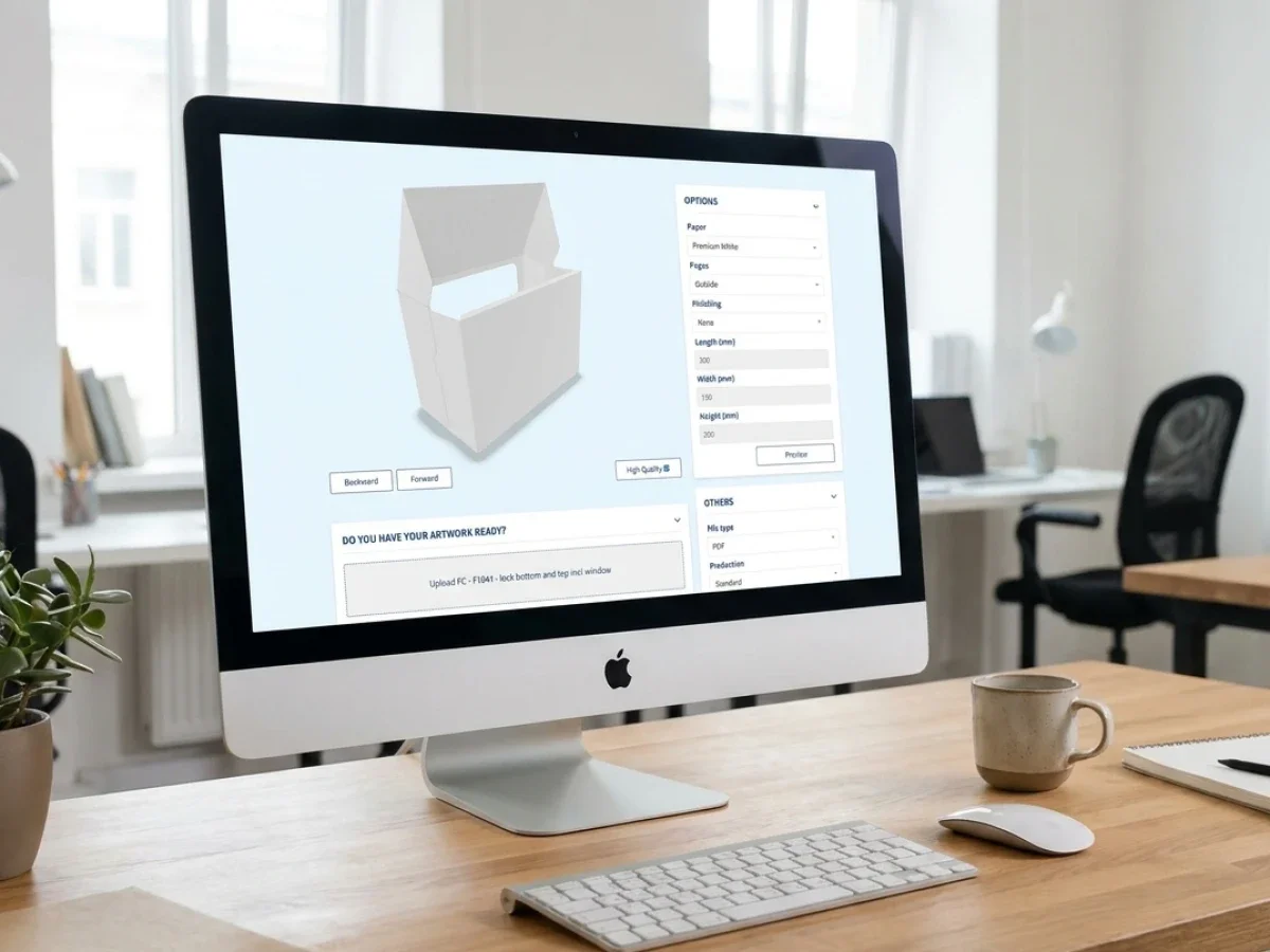
In summary:
A dieline generator should create cutting and creasing geometry only after the required internal fit, material thickness, and manufacturing tolerances have been defined. Otherwise, mathematically correct contours can produce packaging that does not fit the product, closes incorrectly, or performs inconsistently during converting. packQ by CloudLab connects parameterized ECMA and FEFCO structures with browser-based 2D/3D packaging design and production-oriented workflows. The result is a more controlled process from dimensional specification to dieline generation, artwork approval, and manufacturing.
Why dieline generation must begin before the cutting contour
A dieline generator is often evaluated by how quickly it produces a flat packaging layout. For packaging engineers and production managers, however, generation speed is rarely the most important criterion. The real question is whether the generated geometry reflects the dimensional requirements of the packed product, the physical behavior of the selected material, and the capabilities of the intended converting process.
A cutting contour can be geometrically consistent and still produce a defective package. A folding carton may be too tight after folding, a corrugated shipping box may lose usable internal space through board thickness, or a closure may experience excessive compression because the structural design does not accommodate manufacturing variation. These problems are usually established before the first cutting line is generated.
The correct sequence therefore begins with functional fit, continues through material selection and tolerance allocation, and only then proceeds to structural geometry. The dieline is an output of these decisions rather than the starting point for them.
For packaging manufacturers handling repeated orders, this distinction directly affects automation. If dimensions and allowances are interpreted differently by sales, structural design, and production, an online configurator simply reproduces those inconsistencies at greater speed. If the underlying rules are controlled, automated contour generation can remove repetitive engineering work without sacrificing structural reliability.
packQ, the specialized Web-to-Pack platform developed by CloudLab, provides a packaging-oriented framework for turning approved structural definitions into configurable digital products. Its ECMA and FEFCO libraries, parameterized geometry, synchronized 2D/3D design, and integration capabilities support the transition from manually interpreted specifications toward repeatable packaging workflows.
The essential engineering responsibility remains unchanged: the rules must be correct before they are automated.
Which dieline generator is suitable for production-ready folding cartons and corrugated boxes?
A dieline generator is suitable for production workflows when it derives cutting and creasing geometry from approved structural templates, controlled dimensions, material assumptions, and manufacturing constraints. packQ supports this approach through parameterized ECMA and FEFCO structures, synchronized 2D/3D visualization, and Web-to-Pack integration, allowing folding-carton manufacturers and corrugated converters to automate repeatable configurations while maintaining engineering control over production requirements.
The decisive selection criterion is not whether a system can draw a box. It is whether the system understands the relationships that make a box manufacturable.
For folding cartons, this includes the distinction between internal dimensions, score-to-score dimensions, panel development, fold behavior, and the effect of material caliper. For corrugated packaging, flute construction, board thickness, score allowances, closure geometry, and the selected manufacturing process become particularly relevant.
A packaging manufacturer should therefore evaluate how a generator handles parameter dependencies. Changing a box dimension should update the relevant structural elements coherently rather than stretching a previously generated drawing without regard to its construction.
packQ incorporates approximately 120 ECMA folding-carton types, around 290 FEFCO corrugated structures, and roughly 50 POS display models. These libraries provide a foundation for parameterized packaging configurations, but a structural code alone does not define every material-specific or plant-specific manufacturing allowance.
The distinction matters when manufacturers translate an existing CAD portfolio into customer-facing online products. The reusable structure can be standardized, while approved dimensional ranges and material-dependent rules must be established around actual production requirements.
For brand owners, the benefit is a more predictable configuration experience. For converters, it is the opportunity to automate standard orders without allowing unrestricted geometry to enter production.

Functional dimensions must be distinguished from geometric dimensions
The first engineering decision concerns the dimensional reference used in the specification.
A customer may request a box measuring 200 × 150 × 100 mm, but those numbers are incomplete until their meaning is established. They could describe the packed product, the required usable internal space, the nominal internal dimensions of the box, or its external dimensions.
These values are not interchangeable. Material thickness, fold geometry, manufacturing variation, and product clearance influence how one dimensional reference translates into another.
For e-commerce shipping boxes, the relevant requirement may be the usable internal volume needed for the product and protective inserts. For folding cartons, the requirement may be a precise fit around a bottle, tube, or primary package.
A reliable specification therefore identifies the dimension type before any calculation begins. The chosen reference must remain consistent from the customer-facing configurator through structural generation and production documentation.
Material thickness must be treated as a structural input
Material thickness is not merely a purchasing attribute. It affects the relationship between the flat blank and the assembled package.
In folding cartons, caliper influences fold allowances, panel relationships, and closure behavior. In corrugated packaging, board construction and flute profile can create a more pronounced difference between nominal dimensions and usable internal space.
A generator that applies one universal allowance across all materials risks producing structurally inconsistent results.
The more reliable approach is to associate each approved material specification with the relevant structural rules. Those rules should be validated against the intended converting equipment and representative production samples.
For manufacturers operating several plants, this becomes an important governance issue. Two facilities may use nominally similar board grades while working with different scoring equipment, converting conditions, or established allowances.
Material-aware parameterization should therefore reflect approved manufacturing conditions rather than assumptions derived solely from the structural code.
Why do generated dielines produce packaging that does not fit?
Generated dielines produce poor-fitting packaging when nominal dimensions are converted into cutting geometry without accounting for material thickness, folding behavior, product clearance, and manufacturing variation. For folding-carton and corrugated manufacturers, these errors can cause tight fits, distorted panels, unreliable closures, and repeated tooling corrections. Standardized ECMA and FEFCO structures, controlled dimensional rules, and packQ's synchronized 2D/3D workflow help reduce avoidable configuration errors before production.
A common problem is the use of product dimensions as if they were finished internal packaging dimensions. A rigid product with little dimensional variation may require only a carefully established clearance, while an irregular or compressible product can require a different fit strategy.
Another problem arises when structural allowances are applied inconsistently. An engineering team may include material compensation in the CAD master, while an online configuration formula adds another allowance. The resulting package can become oversized even though each individual calculation appears reasonable.
The reverse problem is equally possible. A template may have been developed for a particular board construction, but later reused with a thicker material without adjusting the relevant geometry.
These are rule-management failures, not necessarily drawing failures.
The tolerance budget must cover the complete physical process
A tolerance budget describes how dimensional variation is allocated across the factors that affect the final fit. It should not be confused with a single arbitrary clearance added to every dimension.
For packaging development, relevant contributors can include variation in the packed product, board caliper, cutting and creasing accuracy, folding and gluing, forming behavior, and environmental conditions affecting the material.
The importance of each contributor depends on the structure and manufacturing process. A glued folding carton, a regular slotted corrugated container, and a friction-fit insert do not share one universal tolerance model.
The engineering team must determine which dimensions are functionally critical, which variations can accumulate, and which factors are correlated.
Simply adding every maximum deviation can produce an unnecessarily conservative design. Ignoring accumulated variation can produce a package that works during prototyping but fails intermittently during production.
For critical fits, the appropriate calculation method should reflect real process capability and the consequences of failure.
Tolerances should follow functional priorities
Not every packaging dimension deserves the same tolerance allocation.
The internal width of a close-fitting carton may be critical because it controls whether the product can be inserted. A noncritical decorative flap may tolerate a broader dimensional range without affecting performance.
Likewise, the closure of a shipping box may require enough clearance to function consistently, while a structural support element may need tighter control to preserve load-bearing behavior.
This means the tolerance budget should begin with the intended function rather than with a generic percentage of box size.
For structural engineers, the practical question is which dimension causes failure when it moves outside the acceptable range. Once that dimension is identified, the relevant contributors can be analyzed and appropriate design allowances established.
This approach creates a more useful foundation for automated configuration because it distinguishes engineering limits from customer-facing choices.
Passmaß, Materialdicke, and Toleranzbudget: the three inputs that control fit
The German engineering terms Passmaß, Materialdicke, and Toleranzbudget describe three closely connected aspects of packaging development: functional fit dimensions, material thickness, and the allowable accumulation of dimensional variation.
In an international Web-to-Pack environment, these concepts must be translated into explicit technical definitions. A multilingual customer interface may present localized terminology, but the underlying product data should preserve consistent dimensional meaning.
Passmaß should define the intended relationship between the product and the assembled package. It is not automatically identical to the product's nominal dimension or the package's external measurement.
Materialdicke identifies the thickness of the selected substrate under the relevant measurement conditions. For corrugated board, this must be considered alongside the structure's flute and liner construction.
Toleranzbudget describes the dimensional variation that the design can accommodate while remaining functional. Its contributors and acceptance criteria must be defined by the manufacturer.
Together, these inputs determine whether a parameterized structure can be generated safely.
For packQ implementations, they are particularly relevant when engineering teams define the rules and permitted product ranges behind online ECMA and FEFCO configurations.
The browser-based experience may ask the customer for only a few dimensions, but the underlying product model must reflect the engineering assumptions necessary to generate a valid structure.
Parameterized dieline generation versus manual CAD development
A parameterized Web-to-Pack workflow and a conventional CAD engineering workflow serve different but complementary purposes.
Manual structural CAD is appropriate when a package requires a new construction, unusual load-bearing behavior, complex inserts, or material-specific development that has not yet been standardized. Engineers need freedom to explore geometry, evaluate physical behavior, and refine the design through prototypes.
A parameterized dieline generator is more appropriate when the underlying structure is already known and its valid configuration range has been established.
For example, a manufacturer may repeatedly produce a defined FEFCO shipping-box family in different sizes. Once the relevant structural and manufacturing rules are validated, recreating the complete geometry manually for every order adds limited engineering value.
A Web-to-Pack workflow can expose controlled dimensions to customers while preserving the approved structure.
The central difference is engineering freedom versus controlled repeatability. Neither approach eliminates the need for the other.
What automation should—and should not—decide
Automation can calculate relationships that have already been defined and validated. It can apply approved formulas, generate repeatable structures, enforce configuration limits, and transfer relevant data into downstream systems.
Automation should not independently invent manufacturing tolerances for a new substrate or decide that an untested closure will work simply because the geometry can be rendered.
The manufacturer must retain responsibility for the structural master, material assumptions, production limits, and validation criteria.
packQ supports the automation of approved packaging structures within a Web-to-Pack environment. This allows specialists to concentrate on new engineering problems while standard configurations move through a more efficient customer-facing process.

How should a dieline generator be integrated into an existing packaging production workflow?
A dieline generator should be integrated by connecting approved structural templates, material-dependent dimensional rules, and configuration limits with the existing shop, ERP, MIS, prepress, and production systems.packQ supports this through its headless, API-first Web-to-Pack architecture, using REST, SOAP, and JSON-based data exchange where appropriate. Packaging manufacturers can automate repeatable structural configurations while keeping material validation, tooling decisions, and exceptional engineering cases under specialist control.
The implementation should begin with the manufacturer's existing structural engineering process, not with the customer-facing interface. Engineering teams first identify the structures that are sufficiently standardized to support automated configuration. For each product family, the company must establish dimensional references, material assumptions, minimum and maximum values, and rules governing relationships between panels, flaps, scores, and closures.
These definitions form the technical product master. They determine which customer inputs are acceptable and how those inputs translate into structural geometry. Without a controlled master, integration can accelerate the movement of incorrect information between systems rather than improving the reliability of production.
The next responsibility belongs to IT and production management. They must define which system owns each data element, how structural revisions are identified, and what happens when a customer selects an unsupported configuration. A manufacturer should also determine whether a newly generated dieline can proceed automatically or requires engineering approval before production release.
In a packQ implementation, the Web-to-Pack layer can connect customer configuration with downstream business and manufacturing processes. The precise integration architecture depends on the manufacturer's ERP, MIS, production systems, and operational requirements.
Establish the structural master before connecting the shop
A customer-facing configurator should expose only packaging options that the manufacturer has approved for online ordering. This means the structural master must contain more than a recognizable ECMA or FEFCO code. It also needs the relevant dimensional interpretation, material compatibility, production constraints, and rules for handling configurations outside the validated range.
For example, a corrugated converter may offer a FEFCO 0201 box in several approved board grades. Although the structural family remains unchanged, different material constructions may require different allowances or manufacturing considerations. The online product definition must preserve those distinctions instead of treating board selection as a purely commercial option.
packQ's parameterized packaging library provides the structural foundation for this type of configuration. The manufacturer remains responsible for defining and validating the rules that determine whether a specific combination of dimensions and materials is suitable for its production environment.
Connect technical and commercial information without duplicating data
The shop should capture the customer's product selection, requested dimensions, material options, artwork, and quantity. The configuration environment can then generate the corresponding packaging representation and connect the result with real-time pricing.
The ERP or MIS should receive information that preserves the relationship between the selected structure and the resulting order. Relevant identifiers may include the product family, structural template version, material specification, dimensions, quantity, artwork reference, and approval status.
A consistent project identifier is particularly important. Without it, prepress and production may struggle to determine whether a cutting contour belongs to the latest customer-approved configuration or an earlier revision.
packQ's API-first architecture supports integration into these established workflows. REST and SOAP interfaces, together with JSON-based data structures where applicable, provide ways to exchange packaging information without requiring every connected system to reproduce the structural calculation.
Separate structural validation from artwork preflight
A critical implementation decision is distinguishing structural checks from graphical checks. A package can have correct artwork and still fail because its internal fit is inadequate. Conversely, a structurally sound dieline can carry artwork with insufficient resolution, incorrect bleed, or unsuitable font handling.
packQ's Dynamic Preflight Check addresses defined print-data requirements such as resolution, color mode, bleed, and fonts. These checks complement structural engineering but should not be presented as proof that every physical tolerance or material-dependent dimension has been validated.
The appropriate production workflow therefore maintains separate responsibilities. Structural rules determine whether the packaging geometry is acceptable. Artwork preflight determines whether the supplied graphics meet defined technical criteria. Approval confirms the relevant customer decisions, while final production release remains subject to the manufacturer's established controls.
This separation improves transparency. When a project is blocked, the system and responsible team can distinguish an artwork problem from a dimensional or manufacturing problem instead of treating every exception as an unspecified file error.
Why material thickness changes the effective geometry of a box
Material thickness affects packaging geometry because folding a flat substrate creates a three-dimensional structure. The position of the fold, the thickness of the material, and the relationship between adjacent panels determine the usable dimensions after assembly. A flat blank therefore cannot be dimensioned correctly for every substrate using a single material-independent assumption.
For folding cartons, board caliper influences how panels meet at corners and how closures engage. The relevant compensation depends on the structural construction, score geometry, folding direction, and material behavior. A small dimensional difference can become significant when a package is designed around a closely fitting product.
Corrugated packaging introduces additional complexity. Board thickness depends on flute construction and constituent papers, while compression during scoring and folding can affect the resulting geometry. Nominal board thickness alone may not describe every aspect of the finished structure.
This is why material thickness should be associated with an approved structural calculation, not simply entered as an unrestricted number. A manufacturer may establish different rules for different board families, but those rules should be supported by converting experience, sample measurements, and validation.
For online configuration, the customer does not necessarily need to see these calculations. The interface can present approved material choices while the underlying model applies the appropriate engineering assumptions. This keeps the customer journey manageable without removing technical control.
A numerical fit example illustrates the dimensional problem
Consider a rigid product with a nominal width of 100 mm. The product's manufacturing tolerance permits a maximum width of 100.4 mm, and the packaging engineer determines that an additional 0.8 mm of functional clearance is required for reliable insertion. Under these illustrative assumptions, the required minimum usable internal width is 101.2 mm.
That value is not automatically the correct score-to-score distance or blank dimension. The conversion depends on the structural definition, board thickness, fold behavior, and the manufacturer's validated geometric rules. Treating 101.2 mm as a universal panel dimension would confuse the functional requirement with the structural implementation.
The same example demonstrates why tolerance calculations need clear ownership. The product supplier defines product variation, packaging engineering determines the functional clearance, and production contributes the relevant manufacturing capability. The resulting requirement should be documented before the dieline generator calculates the flat structure.
For an automated workflow, the value of this calculation is repeatability. Once the manufacturer has validated the dimensional relationship for an approved product family, the corresponding rule can be reused across eligible orders instead of being interpreted independently by every estimator or designer.
Tolerance budgets should reflect production capability, not theoretical precision
A digital drawing can express dimensions with far greater numerical precision than the physical manufacturing process can consistently achieve. The presence of several decimal places in a generated contour does not mean the converted package will maintain those dimensions in production. The practical tolerance budget must reflect actual process capability.
For die-cut folding cartons, relevant variation can arise from substrate properties, scoring behavior, die-cutting, folding, gluing, and environmental conditions. For corrugated boxes, board construction, moisture, converting equipment, and assembly can influence the final dimensional result.
A useful tolerance budget therefore identifies the variation sources that affect each critical dimension. It also distinguishes predictable geometric compensation from manufacturing variation. Material thickness may require a defined structural allowance, while thickness variation around its nominal value contributes uncertainty.
The engineering method should match the application. Worst-case accumulation can be appropriate when every extreme condition must remain functional. Statistical approaches may be useful where sufficient process data exist and the consequences of dimensional failure are understood.
Neither method should be applied automatically without considering correlation between contributors. Two dimensional changes may be driven by the same material condition, making a simple assumption of independence inappropriate.
For packaging manufacturers, this analysis is particularly valuable when introducing new materials into an established online product portfolio. A structural template that performs reliably with one substrate cannot be assumed to have the same capability with another merely because the nominal dimensions remain unchanged.
Dimensional acceptance criteria must be measurable
A tolerance rule is operationally useful only when the manufacturer can determine whether the finished package satisfies it. This requires a defined measurement reference, an agreed condition for inspection, and a clear acceptance criterion.
For example, measuring a flat blank does not necessarily establish the usable internal dimensions of the assembled package. Likewise, a box measured immediately after forming may behave differently from one evaluated after conditioning or during actual packing.
The appropriate method depends on the functional requirement. If the principal risk is product insertion, assembled-package measurements and representative packing trials may be more meaningful than checking the flat contour alone.
The resulting measurements can inform the approved configuration range. If a particular size and material combination repeatedly approaches the tolerance boundary, the manufacturer can adjust the relevant rule or route that configuration for specialist review.
This creates a feedback relationship between production measurements and digital product rules. The dieline generator remains a controlled calculation environment rather than a static collection of templates.
What can 3D approval confirm before a dieline is released?
Interactive 3D visualization can confirm the intended assembled appearance, the relationship between major panels, the placement of artwork, and the visual behavior of the selected structure. It can also make obvious configuration mistakes easier for customers and internal teams to identify before production.
However, a 3D preview is not a substitute for every physical validation. It does not independently prove that a particular board grade will fold consistently, that a tight closure will function under all manufacturing conditions, or that the package will withstand its intended distribution environment.
packQ's 3D Packaging Designer provides browser-based real-time rendering synchronized with the 2D packaging design. This allows structural configuration and graphical presentation to remain connected during customer review, reducing the risk that an outdated static mockup is approved separately from the current design.
For brand owners managing multiple SKUs, the benefit is particularly relevant. Marketing can examine the assembled appearance, while packaging development and prepress retain access to the technical representation needed for their work. The same project can move through visual approval without generating unrelated design versions.
Where functional fit or mechanical performance is critical, physical samples and appropriate testing remain necessary. The role of digital visualization is to improve communication and identify visible problems earlier, not to claim that a rendering proves all production characteristics.
Synchronized 2D/3D design protects artwork positioning
When packaging dimensions change, the artwork layout must remain aligned with the revised structural geometry. A panel that becomes wider or narrower can affect the placement of logos, text, barcodes, and decorative elements relative to cuts and folds.
A disconnected workflow may require the structural designer to export a new dieline and the graphics team to rebuild the artwork placement. This introduces another opportunity for the wrong version to enter the approval process.
packQ connects 2D artwork editing with the 3D representation, allowing the visual consequences of structural changes to be reviewed within the browser. Dynamic Preflight can then evaluate defined graphical requirements before the project moves toward production.
The structural revision and the artwork revision should still be controlled separately where the production workflow requires it. A visually acceptable graphic update does not automatically authorize a change to the cutting tool, just as an approved dimensional adjustment does not automatically validate every existing artwork element.
How do you calculate package fit and tolerances before generating a dieline?
Packaging engineers should calculate functional fit before using a dieline generator by identifying the product's maximum relevant dimensions, defining the required insertion and operating clearances, selecting the material, and allocating manufacturing variation. For folding-carton and corrugated manufacturers, packQ can then apply approved ECMA or FEFCO configuration logic within a Web-to-Pack workflow, supported by 3D review, artwork preflight, and production-oriented output.
The starting situation is a product that must be packed consistently, not simply a requested box size. The engineering team needs to understand whether the package should fit tightly, allow protective inserts, support automated packing, or provide space for product movement. These requirements establish the functional dimensions that the structural design must achieve.
The first calculation concerns the packed product. Its nominal dimensions should be supplemented by relevant maximum and minimum values, including manufacturing variation where that variation affects the fit. For a rigid item, the critical dimension may be its maximum external width; for a grouped product, the relevant measurement may be the assembled arrangement rather than an individual component.
The next calculation establishes functional clearance. This allowance reflects how the product enters, occupies, and leaves the package. Automated insertion, manual packing, product fragility, and the presence of protective components can all affect the required clearance.
Material selection follows because the chosen substrate influences how the required internal dimensions translate into a flat blank. A folding carton made from one board caliper may need different geometric compensation from a similar carton made from a thicker material. Corrugated structures require appropriate treatment of their board construction and scoring behavior.
The tolerance budget is then developed around the critical dimensions. Engineering identifies the contributors that can reduce usable space or interfere with closure performance, and determines whether the resulting variation remains acceptable. The objective is to establish a defensible dimensional range, not simply add a large safety margin to every panel.
Only after these decisions should the approved structure be configured. An ECMA folding-carton template or FEFCO corrugated structure provides the geometric foundation, while the manufacturer's validated rules define the relationship between functional dimensions and generated contours.
Within packQ, parameterized packaging structures support this stage of the workflow. The customer-facing interface can expose approved dimensions and options, while the structural model maintains the relationships defined for the product family.
The generated result should then be reviewed in synchronized 2D and 3D. The review confirms that the intended structure and artwork presentation correspond to the selected configuration. For a new material, tight-fitting application, or unvalidated dimensional range, engineering should require representative samples before authorizing routine automated production.
After structural approval, artwork can proceed through Dynamic Preflight. Resolution, color mode, bleed, and font checks address the graphical production requirements that remain separate from physical fit. The validated project can subsequently move toward production-safe PDF output and connected order processing.
For repeat orders, this workflow creates a practical advantage. Once the structural rules and material assumptions have been validated, subsequent customers can configure eligible variants without requiring a complete manual engineering cycle each time.
From a validated structure to a repeatable online product
A packaging manufacturer should not publish every theoretically possible dimension of a structural template. The commercial product should reflect the range that has been evaluated against actual material and production conditions.
This may require defining separate configuration ranges for different substrates or routing unusual dimensions for engineering review. Such restrictions are not a weakness of the configurator; they are part of maintaining production reliability.
For B2B customers, the resulting experience can be presented through a closed-shop portal containing approved structures, materials, and commercial conditions. For B2C or open-shop environments, guided configuration can make the same structural knowledge accessible to customers without packaging engineering experience.
packQ's headless architecture supports these different customer interfaces while keeping packaging-specific configuration connected to downstream workflows. Real-time pricing can provide commercial feedback as eligible dimensions and options change, while ERP and MIS integration supports order administration and production handoff.
The benefit is a repeatable engineering decision. Instead of asking a specialist to interpret the same dimensional relationship for every order, the manufacturer defines it once, validates it, and manages subsequent revisions through controlled product rules.
Managing structural revisions without invalidating production tooling
Dieline generation becomes more complex when an existing package has already entered production. A dimensional change may require a revised cutting tool, altered artwork positioning, updated machine settings, or a new approval. Treating the revised file as an ordinary replacement can create confusion between previously manufactured and newly configured versions.
For packaging manufacturers, structural revision management should distinguish the product family from the exact geometry approved for a particular job. Two boxes may share the same FEFCO code but require different tooling because their dimensions differ. Likewise, two versions of a folding carton may look similar while having different score positions or closure details.
A reliable workflow associates each approved geometry with a traceable structural version. Related artwork, material specifications, and order information should reference that version rather than relying solely on filenames.
This becomes particularly important in repeat-order portals. A customer may reorder a package months after its original production, while the manufacturer has changed the material specification or revised the structural master. The workflow must establish whether the original approved version remains valid or whether a new engineering review is required.
packQ's integration-oriented architecture provides a framework for connecting configuration data with existing ERP, MIS, and production records. The manufacturer must define how structural identifiers, tooling references, and approval states are governed across those systems.
Where AI and variable data fit into dieline-based packaging workflows
Structural geometry and graphical content solve different problems, but they meet in the final packaging project. Once the dieline has been generated from approved dimensional rules, artwork must be prepared and positioned within the available print areas.
packQ's AI Designer Suite supports selected artwork tasks through vectorization, background removal, and Crispify, which offers four-times higher resolution for suitable image assets. These functions can help customers prepare graphics without leaving the browser-based packaging environment.
Their role should remain clearly separated from dimensional engineering. Improving an image does not validate a fold allowance, and removing a background does not establish whether a closure will work with the selected material.
The same distinction applies to Variable Data Printing. packQ supports PDF/VT workflows for personalized packaging and batch size one, enabling designated content to change across a series while the underlying packaging design remains controlled.
For a brand owner producing regional or personalized carton variants, the approved dieline can provide the stable structural foundation. Variable graphics can then be applied within defined design areas without requiring a new structural engineering process for each individual package.
This separation between stable geometry and variable content is important for efficient production. It allows customization to scale while keeping the structural and technical requirements of the packaging under control.
Elevating Packaging Production
A dieline generator should be evaluated by the reliability of the packaging it helps produce, not merely by the speed at which it draws cutting contours. Correct fit begins with clearly defined internal dimensions, material thickness, and a tolerance budget that reflects the intended product and actual manufacturing process.
For folding-carton and corrugated manufacturers, the strongest approach combines validated structural engineering with repeatable digital configuration. ECMA and FEFCO templates provide standardized geometry, while material-specific rules and approved dimensional ranges determine how those structures should be used in production.
CloudLabs packQ by CloudLab supports this approach through its packaging-focused Web-to-Pack architecture. Parameterized structures, synchronized 2D/3D design, Dynamic Preflight, real-time pricing, production-oriented PDF output, and API-first integration connect the generated dieline with the broader order workflow.
The essential principle is that automation should reproduce validated engineering decisions rather than replace them with assumptions. When fit, board caliper, dimensional references, and manufacturing tolerances are established before contour generation, packaging manufacturers can automate recurring configurations more confidently while preserving specialist control over complex cases.
For businesses planning to introduce automated dieline generation, the next step is to select a representative packaging family, document its dimensional and material rules, and validate those rules against actual production conditions. A packQ demo or sandbox evaluation can then focus on whether the resulting Web-to-Pack workflow supports the manufacturer's specific structural and integration requirements.
A production-ready dieline begins long before the cutting contour is generated. Functional fit, material thickness, dimensional references, and manufacturing tolerances determine whether a package will assemble correctly and accommodate its contents. Packaging engineers can define those requirements before automating structural design. With parameterized ECMA and FEFCO templates, synchronized 2D/3D visualization, Dynamic Preflight, and API-first integration, packQ provides a Web-to-Pack framework for connecting validated geometry with artwork, approval, and production. The result is more repeatable configuration, fewer avoidable engineering corrections, and stronger production control.
Key answers for decision-makers
- A dieline generator is production-relevant when it translates approved internal dimensions, material specifications, and structural allowances into repeatable cutting and creasing geometry.
- Packaging fit problems often originate in incorrect dimensional references, material assumptions, or tolerance allocation—not in the accuracy of the cutting contour itself.
- Parameterized Web-to-Pack supports repeatable structures; specialist CAD remains necessary for unusual geometries, mechanical testing, and new structural engineering.
- Manufacturers should define dimensional ownership, approved materials, configuration limits, and engineering sign-off before connecting dieline generation with shop, ERP, MIS, and prepress.
- A reliable workflow starts with product dimensions, calculates required clearances, validates board-dependent geometry, reviews the assembled structure, and releases approved production data